IntuiSwitch™
Turnout Controllers by ESELCO
The Classic IntuiSwitch™ Control
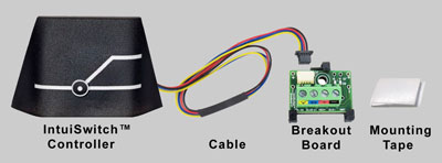
What's included in the package:
How it looks mounted on the fascia:
 Front view. |
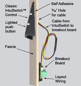 Side view. |
IntuiSwitch™ turnout controls answer your search for an attractive, easily installed and easy to use method of controlling model railroad turnouts activated by Tortoise™ stall motor switch machines.
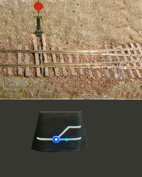
The angled face of our Classic IntuiSwitch™ control makes it easy to see when mounted on a vertical fascia. The curved wings of the housing have no sharp edges or protrusions to catch on clothing or jewelry.
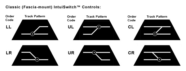
The turnout status is shown by lights behind the track pattern on the face of the control. The controls are available in six different track patterns, allowing you to match the track patterns of your layout.
Electronics inside the Intuiswitch translate the press of the illuminated, tactile pushbutton into the proper drive signal for the switch machine. It displays the current turnout position through the backlit housing. When you shut down your layout at the end of the day, the controller remembers the current position of the switch. When you start your next session, the turnout comes up in the same position, correctly shown on the built-in display.
Installation is quick and easy with a drill and screwdriver -
no soldering needed. This one-minute
video demonstration  shows how easy it is to mount the controller.
Available in different output types. Our standard unit directly drives a Tortoise™ switch motor, while our -H (hybrid) version works with external JMRI or DCC decoder boards which drive the turnouts. To the user, they provide the same consistent interface, allowing a mix of stand-alone and automated turnouts on the same layout. The -H version can be used with non-stall-motor turnout types when paired with an external JMRI or DCC decoder which supports those types.
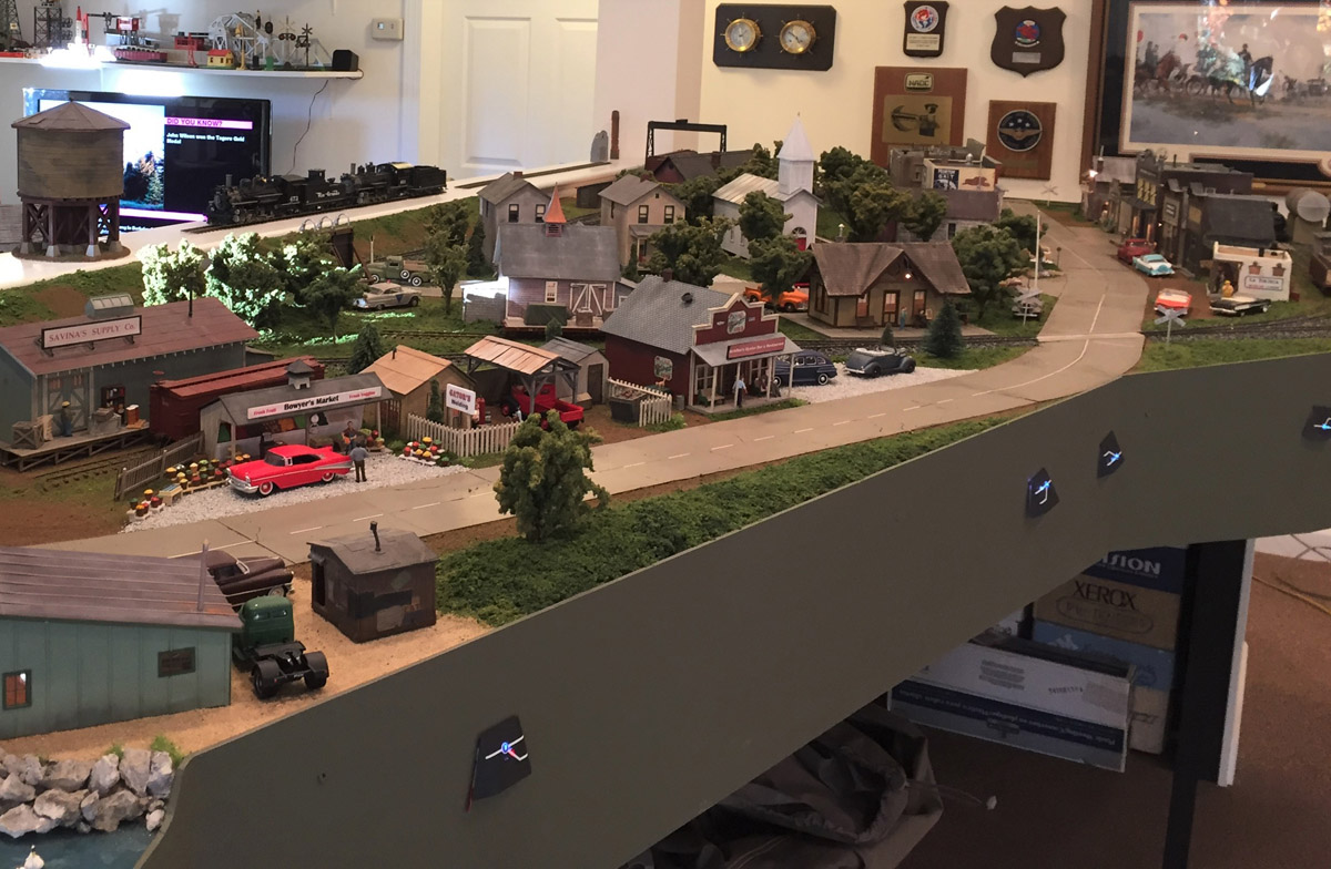
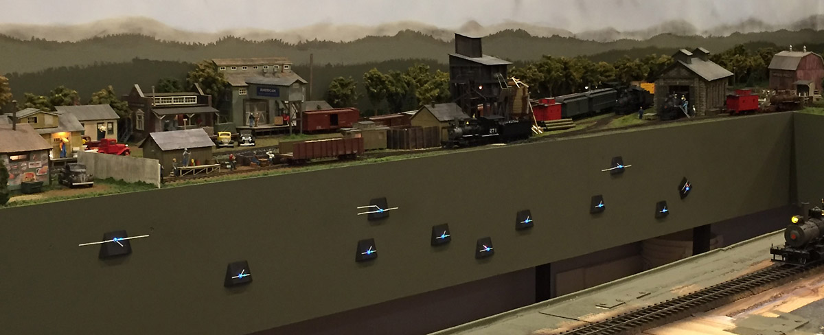
Examples of Classic IntuiSwitch™ Controls in Use:
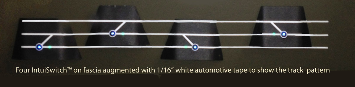
Fascia-mounted IntuiSwitch™ controls mounted near their respective turnouts provide convenient control, as you can see in these photos of the layout of Pete Vollmer (of Williamsburg, VA):
We are now shipping version 2.0 of the IntuiSwitch™ turnout controls.
The V2.0 controls include a screw terminal breakout board that simplifies
connecting layout wiring to the controller. Other features include improved output drive,
reduced light leakage, user customizable pushbutton brightness, and a lockout
feature for layouts at used at public train shows.
Installation is simple:
Mounting the Classic IntuiSwitch™ Control
- Drill a small hole (5/16 inch is sufficient) in the fascia to accomodate the four-wire cable.
- Remove the red lining from the permanent self-adhesive strips on the back of the control
- Insert the four-wire cable through the hole in the fascia
- Push the control firmly onto the fascia
Wiring the Classic IntuiSwitch™ Control
The following instructions are for wiring a standard IntuiSwitch control, which directly drives a stall motor switch machine. If you are installing a -H (hybrid) IntuiSwitch control, see the instructions in the IntuiSwitch-H 2.0 Wiring Quick Reference Guide instead.
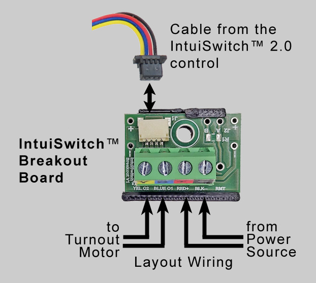 Choose a location for the wiring breakout board, which provides an interface between
the 8" cable attached to the IntuiSwitch controller and your layout wiring.
You can secure the breakout board to the benchwork using a number 4 wood screw or
the supplied mounting tape, before or after attaching the wires.
Choose a location for the wiring breakout board, which provides an interface between
the 8" cable attached to the IntuiSwitch controller and your layout wiring.
You can secure the breakout board to the benchwork using a number 4 wood screw or
the supplied mounting tape, before or after attaching the wires.- Insert the four-wire cable connector from the IntuiSwitch controller into the white connector on the breakout board, with the cable oriented so the black wire is adjacent to the mounting screw hole of the breakout board. Hold the cable parallel to the breakout board when inserting or removing the cable.
- Run wires from your power source (12 to 24 volt DC or 10-16 volt AC, or DCC track power to the red and black terminals. (If using DC, wire + to the red terminal, - to the black terminal.)
- Run wires from the yellow and blue terminals to the stall motor switch machine.
The controls are available in the following standard track patterns:
You can download these Classic (Trapezoidal) IntuiSwitch™ Layout/Mounting Templates to see how they would fit on your layout.
Pricing: Classic-style IntuiSwitch™ V2.0 Controls are $15.95 each.
We accept payment via PayPal and major credit cards.